Kia Seltos: Maintenance / Fuses
Contents:
The electrical system of the Kia Seltos is protected from overload damage by fuses. These fuses are designed to interrupt the circuit when excessive current is detected, helping protect wiring, electrical components, and control systems.
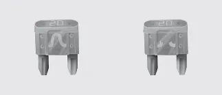
Blade type
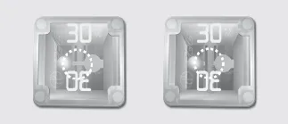
Cartridge type
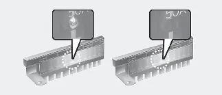
Multi fuse
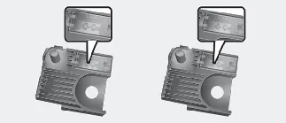
BFT
* Left side: normal, right side: blown.
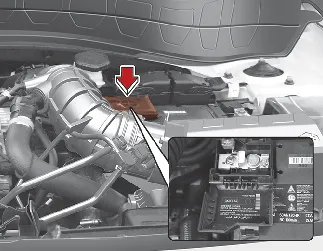
The Kia Seltos is equipped with 2 or 3 fuse panels, depending on equipment. One fuse panel is located in the driver's side panel bolster, and another is located in the engine compartment near the battery.
If any lights, accessories, or electrical controls in your Kia Seltos stop working, check the appropriate circuit fuse first. When a fuse is blown, the internal element inside the fuse melts and opens the circuit.
If the electrical system does not operate correctly, begin by checking the driver's side fuse panel.
If a replacement fuse blows again, this usually indicates an electrical problem. Do not continue using the affected system, and consult an authorized Kia dealer as soon as possible.
Three main types of fuses are used: blade-type fuses for lower amperage circuits, cartridge-type fuses, and multi fuses for higher amperage circuits.

WARNING
Fuse replacement
-
Never replace a fuse with anything other than a fuse of the same amperage rating.
-
Using a higher-capacity fuse may cause electrical damage and could result in a fire.
-
Never install wire, aluminum foil, or any substitute in place of the correct fuse, even as a temporary repair. This can cause extensive wiring damage and may lead to a fire.
-
Do not modify or add electrical wiring to the Kia Seltos arbitrarily.

NOTICE
-
Before replacing a fuse, turn the ignition OFF, switch off all electrical devices, and disconnect the negative (-) battery terminal.
-
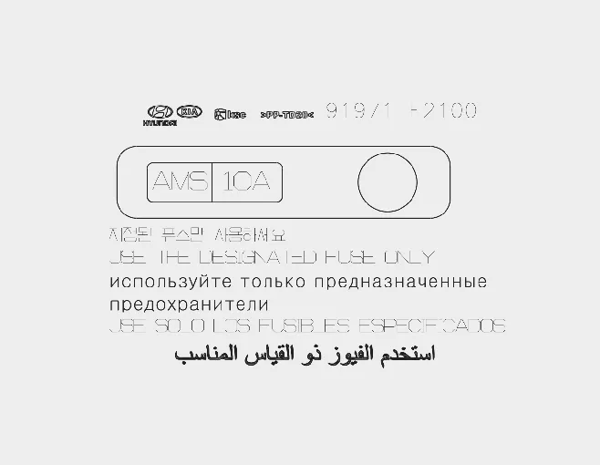
The actual fuse and relay panel label may differ depending on the Kia Seltos equipment and market specification.

WARNING
Electrical Fire
Always make sure that replacement fuses and relays are installed securely in the Kia Seltos. If a fuse or relay is loose or not seated correctly, it may create poor contact, overheating, electrical damage, or a vehicle fire.
Do not remove fuses, relays, or terminals that are fastened with bolts or nuts. These parts may not be reinstalled securely, which can create a fire risk. If a bolted or nutted fuse, relay, or terminal is blown, have the system inspected and repaired by an authorized Kia dealer.

CAUTION
When replacing a blown fuse or relay, make sure the new fuse or relay fits tightly into the clips. If it is not installed securely, the wiring and electrical systems of the Kia Seltos may be damaged.

CAUTION
-
Do not insert objects other than proper fuses or relays into fuse or relay terminals. Using items such as screwdrivers, wires, or other objects may cause contact failure and system malfunction.
-
Do not insert screwdrivers or aftermarket wiring into terminals designed only for fuses and relays. The interior electrical system and wiring of the vehicle may be damaged or burned because of poor contact.
-
If wiring is connected directly to the taillight, or if an over-capacity bulb is installed for trailer use or other modifications, the inner junction block may overheat and burn.

WARNING
Electrical wiring repairs
All electrical repairs on the Kia Seltos should be performed by authorized Kia dealerships using approved Kia parts. Using other wiring components, especially when installing multimedia equipment, theft alarm systems, car phones, radios, or similar accessories, may damage the vehicle and increase the risk of an electrical fire.

NOTICE
Rewiring Prohibited
Do not rewire your Kia Seltos in any way. Rewiring may affect the performance of important safety features, cause electrical system problems, and may void the vehicle warranty. Any damage that results from unauthorized rewiring may become the owner's responsibility.
Fuse/relay panel description
The fuse and relay panel covers on the Kia Seltos contain labels that identify each fuse and relay, along with their corresponding names and amperage ratings. These labels help owners quickly locate and identify electrical circuits when performing inspections or replacing a fuse.

NOTICE
Not all fuse panel descriptions shown in this manual may apply to every Kia Seltos model. The information was accurate at the time of publication. When inspecting the fuse panel in your vehicle, always refer to the fuse panel label located inside the fuse cover. This label contains the exact configuration and circuit information for your specific Kia Seltos.
Driver's side fuse panel
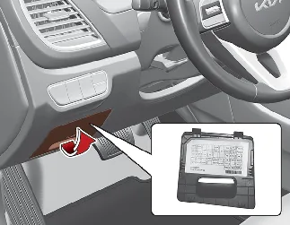
The following table provides a description of the fuses installed in the instrument panel fuse box located on the driver's side of the Kia Seltos.
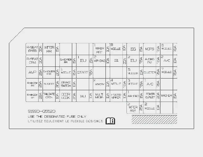
Instrument panel (Driver's side fuse panel)
|
Fuse Name |
Fuse Rating |
Circuit Protected |
|---|---|---|
P/SEAT (PASS) |
30 A |
Passenger Seat Manual Switch |
P/SEAT (DRV) |
30 A |
IMS (Driver's Memory Seat) Control Module, Driver Seat Manual Switch |
AMP |
25 A |
Low DC-DC Converter, Audio Amplifier System |
P/WINDOW RH |
25 A |
Right-Side Power Window Relay |
P/WINDOW LH |
25 A |
Left-Side Power Window Relay, Driver Safety Power Window Module |
WIPER RR |
15 A |
Rear Wiper Motor, Rear Wiper Relay |
S/HEATER FRT |
20 A |
Front Seat Warmer Control Module |
SUNROOF |
20 A |
Sunroof Control Unit |
TAILGATE OPEN |
10 A |
Power Tailgate / Liftgate Relay |
S/HEATER RR |
15 A |
Rear Seat Warmer Control Module |
MODULE 1 |
7.5 A |
Hazard Switch, Data Link Connector, Power Window Controls, Power Liftgate Module, IMS Control Module, Key Interlock System |
BRAKE SWITCH |
10 A |
Stop Lamp Switch, Integrated Body Control Unit (IBU) |
DOOR LOCK |
20 A |
Door Lock Relay, Door Unlock Relay, Two-Turn Unlock Relay |
IBU 1 |
15 A |
Integrated Body Control Unit (IBU) |
START |
7.5 A |
Burglar Alarm Relay, Transmission Range Switch (Smartstream G1.6 T-GDi), Position Switch ((Gasoline) 2.0 MPI) |
IAU |
10 A |
Identity Authentication Unit (IAU), Driver and Passenger NFC Modules |
WIPER FRT 1 |
10 A |
Integrated Body Control Unit (IBU) |
AIR BAG 2 |
10 A |
SRS (Supplemental Restraint System) Control Module |
MEMORY 2 |
10 A |
Air Conditioner Control Module, Crash Pad Switches, Mood Lamp Unit |
MULTIMEDIA |
15 A |
Low DC-DC Converter and Multimedia Components |
MODULE 8 |
10 A |
Identity Authentication Unit (IAU) |
IG1 |
25 A |
ABS, EPB, ECU, and TCU Related Circuits |
MODULE 4 |
7.5 A |
Front Radar, Front View Camera, AWD ECM, Crash Pad Switches, IBU |
HEATED MIRROR |
10 A |
Engine Control Module, Air Conditioner Control Module, Heated Outside Mirrors |
ISG |
15 A |
Mood Lighting, Rear Corner Radar Sensors, Wireless Charger, Infotainment System, Instrument Cluster, Amplifier |
IBU 2 |
7.5 A |
Integrated Body Control Unit (IBU) |
MODULE 5 |
10 A |
Electrochromic Mirror, Wireless Charger, Audio System, Amplifier, Climate Controls, Driver Memory Seat System |
MODULE 3 |
7.5 A |
Stop Lamp Switch, Automatic Transmission Shift Lever |
AIR BAG 1 |
15 A |
SRS Control Module, Passenger Occupant Detection Sensor |
WIPER FRONT 2 |
25 A |
Front Wiper Relay and Front Wiper Motor |
MDPS |
7.5 A |
Motor Driven Power Steering (MDPS / EPS) Unit |
A/BAG IND |
7.5 A |
Overhead Console Lamp, Instrument Cluster |
CLUSTER |
7.5 A |
Instrument Cluster |
A/C 1 |
7.5 A |
Blower Relay, PTC Heater Relays, Air Conditioner Control Module |
POWER OUTLET |
20 A |
Front Power Outlet #2 (USB) |
MODULE 2 |
10 A |
IBU, USB Charging Ports, Power Mirror Switches, Rear USB Charger, Power Outlet Relay |
MODULE 6 |
7.5 A |
Integrated Body Control Unit (IBU) |
A/C 2 |
10 A |
Blower Motor, Blower Resistor, Air Conditioner Control Module |
MODULE 7 |
7.5 A |
Front Deicer Relay System |
WASHER |
15 A |
Multifunction Switch and Washer System |
This fuse panel layout helps Kia Seltos owners quickly identify electrical circuits and simplify troubleshooting. Always replace a blown fuse with one of the same amperage rating and consult an authorized Kia dealer if the same fuse repeatedly fails.
Additional note: Proper fuse maintenance helps ensure reliable operation of safety systems, lighting, multimedia features, and comfort functions throughout the life of your Kia Seltos.
Engine compartment fuse panel
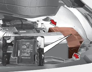
The engine compartment fuse panel of the Kia Seltos contains a variety of high-capacity fuses and relays that protect critical electrical systems. Use the information below to identify fuse locations, ratings, and the circuits they safeguard. Always consult the label inside the fuse cover before replacing any component.
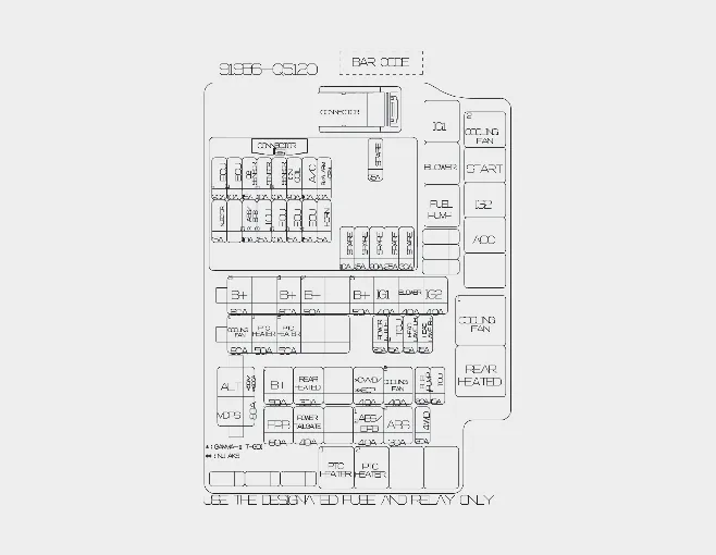
Engine Room Junction Block
Fuse |
Fuse Name |
Fuse Rating |
Circuit Protected |
|---|---|---|---|
MULTI FUSE-1 |
ALT |
150 A / 200 A |
Alternator, EPB, ABS, Power Tailgate, AWD System and Engine Room Junction Block Power Distribution. |
MDPS |
MDPS |
80 A |
Motor Driven Power Steering Unit. * MDPS is equivalent to EPS (Electric Power Steering). |
MULTI FUSE-2 |
B+3 |
60 A |
Instrument Panel Junction Block Power Supply (IPS1, IPS2, IPS3, IPS7, IPS10, IPS13, IPS20). |
B+4 |
B+4 |
60 A |
Power Seats, Amplifier, Power Windows, Seat Heaters, Sunroof and Power Tailgate Systems. |
B+2 |
B+2 |
50 A |
Additional Instrument Panel Junction Block Power Circuits. |
B+5 |
B+5 |
50 A |
Main Relay, Air Conditioning, Alarm Horn, ECU and Horn Circuits. |
IG1 |
IG1 |
40 A |
[With Smart Key] IG1 Relay and ACC Relay. [Without Smart Key] Ignition Switch Circuit. |
BLOWER |
BLOWER |
40 A |
HVAC Blower Relay and Climate Control Blower Motor Circuit. |
IG2 |
IG2 |
40 A |
Start Relay and Ignition Related Systems. |
MULTI FUSE-3 |
COOLING FAN 1 |
80 A |
[Smartstream G1.6 T-GDi] Cooling Fan Motor Circuit. |
PTC HEATER 1 |
PTC HEATER 1 |
50 A |
PTC Heater Relay #1. |
PTC HEATER 2 |
PTC HEATER 2 |
50 A |
PTC Heater Relay #2. |
FUSE |
POWER OUTLET |
25 A |
Power Outlet Relay and Accessory Socket Circuit. |
TCU 2 |
TCU 2 |
15 A |
[Smartstream G1.6 T-GDi] Transmission Control Module. |
HEAD LAMP LH |
HEAD LAMP LH |
15 A |
Left Headlamp Circuit. |
HEAD LAMP RH |
HEAD LAMP RH |
15 A |
Right Headlamp Circuit. |
B+1 |
B+1 |
50 A |
Seat Heaters, Door Locks, Air Bag Modules, IBU, Brake Switch and Related Systems. |
REAR HEATED |
REAR HEATED |
30 A |
Rear Window Defogger Relay. |
CVVD/EOP |
CVVD/EOP |
40 A |
[Smartstream G1.6 T-GDi] CVVD Actuator. [(Gasoline) 2.0 MPI] Electronic Oil Pump Module. |
COOLING FAN 2 |
COOLING FAN 2 |
40 A |
Cooling Fan Relays and Auxiliary Cooling Fan Circuit. |
FUEL PUMP |
FUEL PUMP |
20 A |
Fuel Pump Relay Circuit. |
FUSE |
TCU 1 |
15 A |
PCM and TCM Control Circuits. |
EPB 1 |
EPB 1 |
60 A |
Electronic Parking Brake / ESC Module. |
POWER TAILGATE |
POWER TAILGATE |
40 A |
Power Liftgate Module. |
ABS 1 / EPB 2 |
ABS 1 / EPB 2 |
40 A |
Electronic Stability Control and Anti-lock Braking System Circuits. |
ABS 2 |
ABS 2 |
30 A |
ESC Module (Vehicles without Electronic Parking Brake). |
4WD |
4WD |
20 A |
AWD Control Module. |
PCB Block
Fuse Name |
Fuse Rating |
Circuit Protected |
|---|---|---|
ECU 1 |
20 A |
Engine Control Module or Powertrain Control Module depending on engine specification. |
ECU 2 |
10 A |
Engine Control Module Power Supply. |
O2 SENSOR |
15 A |
Upstream and Downstream Oxygen Sensors. |
SENSOR 1 |
10 A |
Oil Control Valves, Cooling Fan Controls, Purge Solenoid, Variable Oil Pump and Related Sensors. |
SENSOR 2 |
10 A |
Fuel Pump Relay Control Circuit. |
IGN COIL |
20 A |
Ignition Coils 1–4. |
A/C |
10 A |
Air Conditioner Relay. |
B/ALARM HORN |
10 A |
Burglar Alarm Horn Relay. |
INJECTOR |
15 A |
Fuel Injectors (Gasoline 2.0 MPI). |
ABS 3 / EPB 3 |
10 A |
ESC and Electronic Parking Brake Related Circuits. |
TCU 3 |
15 A |
Transmission Control Module or Electric Oil Pump System. |
ECU 5 |
10 A |
Engine Control Module and CVVD Actuator. |
ECU 3 |
15 A |
Engine / Powertrain Control Module. |
ECU 4 |
15 A |
Engine Control Module Circuit. |
HORN |
15 A |
Horn Relay. |
Relay
Refer to the following relay table for relay identification used in the Kia Seltos engine compartment fuse panel.
Relay No. |
Relay Name |
Type |
|---|---|---|
E61 | IG1 Relay | MICRO |
E62 | BLOWER Relay | MICRO |
E63 | FUEL PUMP Relay | MICRO |
E64 | COOLING FAN 2 Relay | MICRO |
E65 | START Relay | MICRO |
E66 | IG2 Relay | MICRO |
E67 | ACC Relay | MICRO |
E69 | COOLING FAN 1 Relay | MINI |
E70 | REAR HEATED Relay | MINI |
E71 | PTC HEATER 1 Relay | MICRO |
E72 | PTC HEATER 2 Relay | MICRO |
The engine compartment fuse box is one of the most important electrical distribution centers in the Kia Seltos. Regular inspection of fuses and relays can help prevent unexpected electrical issues and ensure reliable operation of systems such as AWD, climate control, lighting, engine management, and safety features.
Additional information: For maximum reliability, always use genuine Kia Seltos replacement fuses and relays with the correct amperage rating. Installing incorrect components may affect electrical performance and system protection.
Battery terminal cover
 NOTICE
Not all fuse panel descriptions shown in this manual may apply to your Kia Seltos. The information was accurate at the time of printing. When inspecting the fuse panel in your vehicle, always refer to the actual fuse panel label installed on your Kia Seltos.


Other information:
Kia Seltos SP2 (2021-2026) Owner's Manual: Selecting a CRS
When selecting a Child Restraint System for your child, always choose a restraint that fits the child, fits the Kia Seltos seating position, and can be installed according to the manufacturer's instructions. Make sure the CRS has a label certifying that it meets FMVSS 213. Select a child restraint based on your child's height and weight.Kia Seltos SP2 (2021-2026) Owner's Manual: Navigation-based Smart Cruise Control (NSCC)
Navigation-based Smart Cruise Control (NSCC) in the Kia Seltos can help maintain an appropriate driving speed according to road conditions when driving on highways or motorways. While Smart Cruise Control is operating, NSCC uses road information from the navigation system to support smoother and safer highway driving. NOTICE NSCC is available only on controlled-access roads of certain highways.