Kia K4: Fuses / Fuse/relay panel description
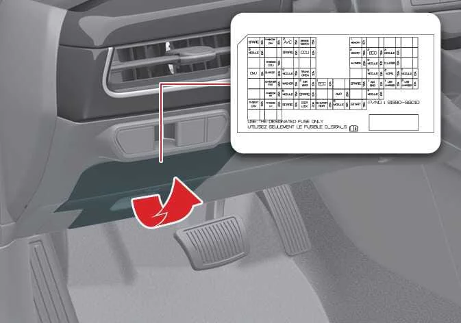
Located on the interior side of the fuse and relay panel covers, you will find a detailed label identifying the function, name, and amperage capacity of each fuse and relay for your Kia K4. This information is essential for troubleshooting electrical systems efficiently.
TIP
While the fuse panel descriptions provided in this manual are accurate as of the printing date, please be aware that minor variations in configuration may occur depending on the specific trim level, production date, and optional equipment fitted to your Kia K4. Always refer to the physical label on your vehicle's fuse panel cover for the most precise information.
Driver side fuse panel
|
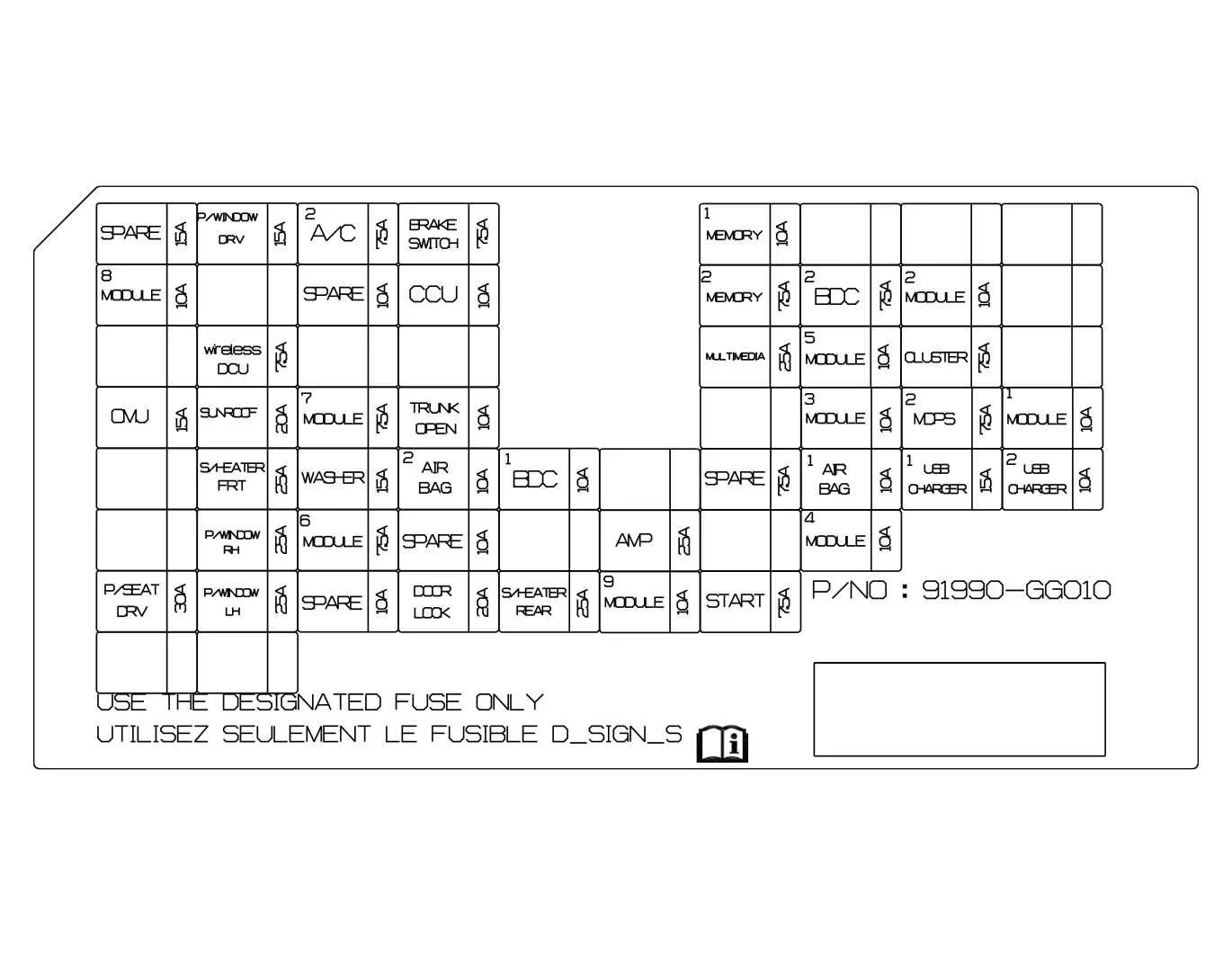
The following table outlines the Power Distribution Center (PDC) fuse configurations for the Kia K4, detailing the specific circuits protected to help you maintain your vehicle's electrical health.
|
Fuse Name |
Fuse rating |
Circuit Protected |
|---|---|---|
A/C2 |
7.5A |
DATC/MTC climate controls, engine room junction block PTC heater relays, and A/C compressor clutch (Smartstream G1.6 T-GDi models). |
AIR BAG1 |
10A |
Airbag Control Unit (ACU), supplemental restraint system components, and Occupant Detection System (ODS). |
AIR BAG2 |
10A |
Secondary Airbag Control Unit (ACU) and associated airbag deployment circuits. |
AMP |
25A |
Premium audio amplifier and low voltage DC-DC converter (LDC) 450 system. |
BDC1 |
10A |
Body Domain Controller (BDC), Bluetooth connectivity unit, UWB system, and transmission lever assembly. |
BDC2 |
7.5A |
Body Domain Controller (BDC) and Battery Management System (BMS) logic. |
BRAKE SWITCH |
7.5A |
Body Domain Controller (BDC) signals and stop lamp switch activation. |
CCU |
10A |
Central Communication Unit (CCU) for vehicle connectivity. |
CLUSTER |
7.5A |
Instrument cluster display and warning indicators. |
DOOR LOCK |
20A |
Door lock/unlock relay actuators and two-turn unlock logic. |
MDPS2 |
7.5A |
Motor Driven Power Steering (MDPS) control system logic. |
MEMORY1 |
10A |
Instrument cluster settings, climate control memory, mood lighting, and PDW sensor system. |
MEMORY2 |
7.5A |
Front USB interface jack and wireless charging pad. |
MODULE1 |
10A |
Integrated domain control systems including BDC, CCU, AVN keyboard, E-CALL console, ADAS parking ECU, and CCNC cockpit systems. |
MODULE2 |
10A |
Central Communication Unit (CCU) and E-CALL domain control functions. |
MODULE3 |
10A |
Driver-side power window switch master controls. |
MODULE4 |
10A |
Lane Keeping Assist (LKAS) camera and Advanced Driver Assistance System (ADAS) parking electronics. |
MODULE5 |
10A |
Comprehensive module managing the In-Cabin Camera, CCNC, ECM interior mirror, climate control panel, wireless charging, and lighting switches. |
MODULE6 |
7.5A |
Body Domain Controller (BDC) secondary logic. |
MODULE7 |
7.5A |
Parking Lithium Battery Module (P-LBM) and heated windshield coil circuits. |
MODULE8 |
10A |
Smart key interlock, rain sensor, hazard lights, and cabin monitoring units. |
MODULE9 |
10A |
Power window master switch, Integrated Memory System (IMS) ECU, and Digital Key system. |
MULTIMEDIA |
25A |
Connected Car Navigation & Cockpit (CCNC) and secondary low voltage DC converter power. |
OMU |
15A |
Driver and passenger side power-folding mirror motors. |
P/SEAT DRV |
30A |
Driver-side power seat adjustment motors and memory seat functions. |
P/WINDOW DRV |
15A |
Driver-side power window express up/down relay and motor control. |
P/WINDOW LH
25A
Safety Electronic Control Unit (ECU) for driver, passenger, and left-rear windows; power window switch assembly for rear-left and passenger side.
P/WINDOW RH
25A
Safety Electronic Control Unit (ECU) for driver, passenger, and right-rear windows; power window switch assembly for rear-right and passenger side.
S/HEATER FRT
25A
Front seat heating and ventilation system controls for the Kia K4.
S/HEATER RR
25A
Rear seat heating system elements and control modules.
SPARE
10A
Spare fuse position for emergency replacement or auxiliary circuit installation.
SPARE
15A
Spare fuse position for emergency replacement or auxiliary circuit installation.
SPARE
10A
Spare fuse position for emergency replacement or auxiliary circuit installation.
SPARE
10A
Spare fuse position for emergency replacement or auxiliary circuit installation.
SPARE
7.5A
Spare fuse position for emergency replacement or auxiliary circuit installation.
START
7.5A
Start inhibit relay logic, gear position inhibit switch, and ignition switch signal processing.
SUNROOF
20A
Sunroof motor assembly and tilt/slide control module.
TRUNK OPEN
10A
Trunk lid release actuator relay control.
USB CHARGER1
15A
Rear passenger USB charging port and engine Start/Stop button interface circuit.
USB CHARGER2
10A
Secondary interior USB charging port power supply.
WASHER
15A
Windshield washer pump motor and fluid spray system.
wireless DCU
7.5A
Wireless Domain Control Unit (DCU) responsible for cabin wireless communications.
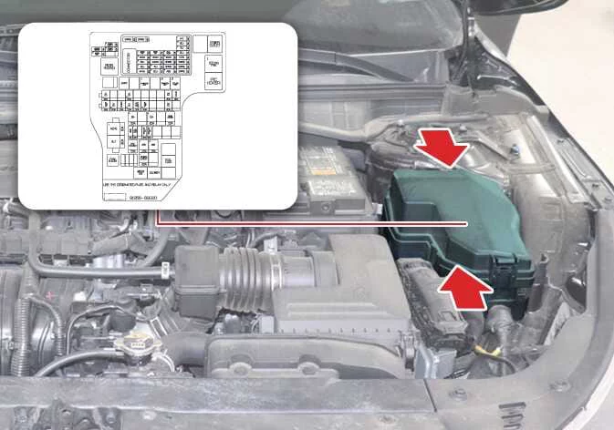
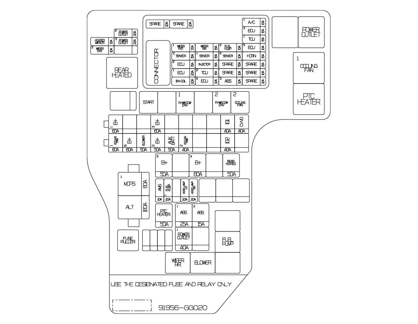
Engine compartment fuse panel
|
|
Fuse Name |
Fuse rating |
Circuit Protected |
|---|---|---|
|
A/C1 |
10A |
Air conditioning compressor clutch relay for the Kia K4. |
|
ABS1 |
25A |
Electronic Stability Control (ESC), Anti-lock Brake System (ABS), and Electronic Parking Brake (EPB) control units. |
|
ABS2 |
15A |
Electronic Stability Control (ESC), Anti-lock Brake System (ABS), and Electronic Parking Brake (EPB) control units. |
|
ABS3 |
10A |
Electronic Stability Control (ESC), Anti-lock Brake System (ABS), and Electronic Parking Brake (EPB) control units. |
|
ALT |
180A |
High-capacity main circuit for alternator output, Mild Hybrid Starter and Generator (MHSG), and Battery (BATT) positive terminal. |
|
AMS |
10A |
Intelligent Battery Sensor (IBS) for precise charge monitoring. |
|
AUX BATT |
50A |
Lithium Battery Module (P-LBM) auxiliary power management. |
|
B+1 |
60A |
Power Distribution Center (PDC) main feed for Intelligent Power Switch (IPS) stages 1 through 6. |
|
B+2 |
50A |
Power Distribution Center (PDC) main feed for Intelligent Power Switch (IPS) stages 8 through 12. |
|
B+3 |
60A |
Main feed for critical interior Kia K4 systems: SPARE, Power Seat, Front Seat Heater, Power Windows, OMU, Sunroof, and wireless DCU. |
|
B+4 |
60A |
Main power feed for door locking, trunk/tailgate release relays, multimedia system, memory modules, body controller, and various switch signals. |
|
B+5 |
50A |
Power distribution for premium audio amplifier, airbag controller, Battery Management System (BMS), and convenience charging ports. |
|
B+6 |
60A |
Main power supply for the Engine Room Junction Block PCB assembly. |
|
BLOWER |
50A |
Heating, Ventilation, and Air Conditioning (HVAC) blower motor relay. |
|
COOLING FAN1 |
80A |
High-current supply for the brushless direct current (BLDC) engine cooling fan. |
|
COOLING FAN2 |
40A |
Cooling fan relay control circuits 1 and 2. |
|
CVVD |
40A |
Continuously Variable Valve Duration (CVVD) system actuator power. |
|
ECU1 |
20A |
Primary Engine Control Module (ECM) supply circuit. |
|
ECU2 |
15A |
Secondary Engine Control Module (ECM) logic and sensor power. |
|
ECU3 |
15A |
Engine Control Module (ECM) power supply circuit, ensuring stable voltage for the Kia K4 engine management system. |
|
ECU4 |
10A |
Dedicated fuse for the Engine Control Module (ECM) secondary logic circuits in the Kia K4. |
|
ECU5 |
10A |
Engine Control Module (ECM) sensor supply line, critical for maintaining engine operational parameters for the Kia K4. |
|
FUEL PUMP1 |
20A |
Primary power feed for the fuel pump relay, controlling high-pressure fuel delivery in the Kia K4. |
|
FUEL PUMP2 |
10A |
Secondary fuel pump control circuit for redundant power delivery to the fuel pump relay. |
|
HEAD LAMP LH |
20A |
Left-hand headlamp illumination circuit, supporting high-intensity lighting for the Kia K4. |
|
HEAD LAMP RH |
20A |
Right-hand headlamp illumination circuit, ensuring optimal road visibility for the Kia K4. |
|
HEATED MIRROR |
15A |
Control circuit for the Electronic Control Unit (ECU) managing the driver and passenger power outside heated mirrors. |
|
HORN |
15A |
Dedicated fuse for the HORN relay system, responsible for acoustic warning signals. |
|
IG1 |
40A |
Main ignition circuit 1, supplying power to the IG1 relay, Accessory (ACC) relay, and Ignition Switch (IGN SW). |
|
IG2 |
40A |
Main ignition circuit 2, powering the IGN SW, IG2 relay, and Start relay components. |
|
IGN COIL |
20A |
Ignition coil primary power circuit, essential for spark generation in the Kia K4 engine. |
|
INJECTOR |
15A |
Fuel injector power supply and Mild Hybrid Starter and Generator (MHSG) signal monitoring circuit. |
|
MDPS1 |
80A |
High-amperage power feed for the Motor Driven Power Steering (MDPS) unit, ensuring steering assist for the Kia K4. |
|
POWER OUTLET1 |
40A |
Main power supply for the Engine Room Junction Block power outlet relay. |
|
POWER OUTLET2 |
20A |
Dedicated circuit for the front passenger power outlet. |
|
POWER OUTLET3 |
20A |
Power supply for the luggage area or rear power outlet socket. |
|
PTC HEATER |
50A |
Positive Temperature Coefficient (PTC) heater relay, providing rapid interior cabin heating for the Kia K4. |
|
REAR HEATED |
50A |
High-load circuit for the rear window defogger and heated glass relay. |
|
SENSOR1 |
15A |
Power supply for the oxygen (O2) sensor assembly. |
|
SENSOR2 |
10A |
Power for various engine management components: OCV, Oil Level Sensor, PCSV, VIS/VOP, RCV/OPSV, and CCV. |
|
SENSOR3 |
15A |
Power circuit for the Cooling Fan Brushless Direct Current (BLDC) motor and associated fan speed relay controls. |
|
SPARE |
15A, 20A, 20A, 7.5A, 10A, 10A, 10A |
Designated spare fuse slots for emergency circuit protection or accessory integration. |
|
TCU1 |
15A |
Power for the 8-speed Automatic Transmission (8AT) or Continuously Variable Transmission (CVT) Transmission Control Unit (TCU). |
|
TCU2 |
15A |
Secondary power supply for the 8AT transmission control module. |
|
WIPER FRT1 |
30A |
Front wiper motor power circuit, including the low-speed wiper relay. |
|
WIPER FRT2 |
10A |
Body Domain Controller (BDC) interface for the front wiper system. |
|
WIPER RR |
15A |
Independent power circuit for the rear windshield wiper motor. |


Other information:
Kia K4 (CL4) 2025-2026 Owner's Manual: Lane Following Assist (LFA)
The Lane Following Assist (LFA) system is a sophisticated driver-assistance feature designed to enhance your comfort and safety. By utilizing advanced sensor technology, the Kia K4 can actively detect lane markings or the position of a vehicle traveling directly ahead. The system then provides subtle steering support to help keep your Kia K4 centered within its lane, significantly reducing driver fatigue during long journeys or highway driving.If your specific vehicle package is configured with the optional premium wide sunroof assembly, you can effortlessly slide open or tilt the glass panel using the multi-stage electronic sunroof switch located conveniently on the overhead console panel. To protect the battery state of charge, you can only actuate the panoramic or wide sunroof tracking system when the ENGINE START/STOP button is placed in the active ON or START power mode positions.
Categories
- Manuals Home
- Kia K4 Owners Manual
- Questions & Answers
- Video Guides
- Useful Resources
- New on site
- Most important about Kia K4
- Privacy Policy